F.Port protocol
Motivation

Until recently I have controlled Naminukas robot either from a desktop computer during development or from a laptop during experiments. Since BeagleBone Blue board can act as WiFi access point it is easy to connect to the robot anywhere even then no other networks are available. When I tried this solution on the beach during bright sunny day I immediately understood drawback: screen readability is severely affected by the direct sunlight. Extensive use of keyboard shortcuts in my web based control UI helped a lot but even finding the right key on the keyboard was a challenge. After all sunglasses (see image on the right) were invented because it is hard to look at anything on the bright sunny day.
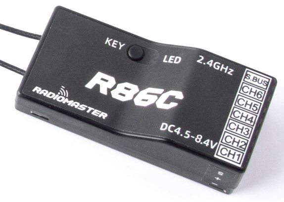
RadioMaster R86C-D8
6/8 Channel
PWM/SBUS receiver
This experience led me to buy not sunglasses but my first hobby RC radio. Dedicated mechanical gimbals and switches makes it natural to move robot without looking at the controls. Given variety of radio brands, protocols, controllers and receivers it was a daunting task to choose what to buy. I ended up with RadioMaster TX16S MAX. My goal was to have 2 way communication between controller and robot. But even after hours of research I ended up buying SBUS capable receiver (see image on the left) just to discover that SBUS supports only controller to receiver communication. I had to bit-bang SBUS protocol in BeagleBone Blue PRU unit. Documentation both about SBUS and PRU is sparse and it took countless hours to get working proof of concept implementation. Eventually I figured out that F.Port capable receiver is what would allow me to have bidirectional communication between controller and the robot. So I bought Jumper R1F F.Port receiver (see setup image bellow). It was not so hard to get it working one way as in a way F.Port is just "better" SBUS. I am still working on getting telemetry from the robot to the controller but I though I should document process so far to help someone on the same journey as I was.
Experimental setup
First, I would like to say that having proper tools to analyse signals was probably more useful than Google on this subject. Here is my setup to debug F.Port signals:
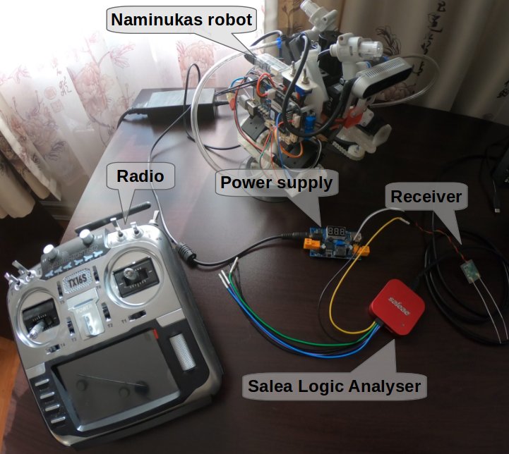
F.Port debugging setup
I was lucky to have access quite expensive but totally worth it piece of equipment called Saleae Logic Analyser. Saleae Logic Analyser allows to capture up to 8 input signals (even more expensive 16 channel version is available too) and display/analyse them on computer via USB connection. It captures both analog and digital signals so it can replace osciloscope in some cases. Computer side software is called Logic and is available for Linux, Mac and Windows. It is very simple and intuitive to use. There is no need to even install it. You just download a single file and run it. What is the most useful in my opinion is the ability to annotate captured signals. For example, it can decode Universal Asynchronous Receiver-Transmitter (UART), Serial Peripheral Interface (SPI) and Inter-Integrated Circuit (I²C) signals and display which part the signal corresponds to which byte. Here is an example of F.Port signal decoded as UART:
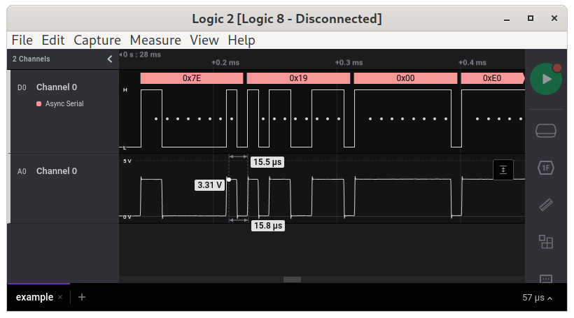
Decoded UART signal
At the bottom "A0" channel shows analog signal which is not interesting for us in this case except to check if device operates at 3.3V or 5V. At the top "D0" channel represents digital signal. At the very top pink boxes indicate decoded UART bytes. White dots indicate where data bits are.
What is F.Port protocol?
F.Port is a single wire bus which uses inverted UART with speed 115200 bits / second, 8 data bits, one start bit, one stop bit and no parity. These are required settings to decode signal in Saleae Logic software:
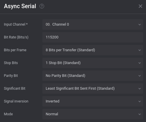
Saleae Logic UART settings
Protocol defines the following 3 frames:
| Head | Len | Type | Channel frame | CRC | End |
|---|---|---|---|---|---|
| 0x7E | 0x19 | 0x00 | [data1][data2] ... [data22][flags][RSSI] | 0x7E |
| Head | Len | Type | Prime | AppId low | AppId high | Data | CRC | End |
|---|---|---|---|---|---|---|---|---|
| 0x7E | 0x08 | 0x01 | 0x7E |
| Len | Type | Prime | AppId low | AppId high | Data | CRC |
|---|---|---|---|---|---|---|
| 0x08 | 0x81 |
Control frame is used to send channel data from radio controller to the receiver. 16 channels as send in 22 "data" bytes. Each channel uses 11 bits. There are 2 additional "digital" only channels which are send as 2 least significant bits of "flags" byte. Not all hardware supports them. "RSSI" byte stands for Received Signal Strength Indicator. "CRC" is summed from "Len" field to the byte in front of "CRC".
Downlink/Uplink data frames is what allows bidirectional communication. I am still working on implementing them in my robot and I will add more information about them here or in the next blog entry in the future.
Saleae Logic Extensions
While UART annotations in Saleae Logic are very useful, it would be even more useful if it could understand not only generic UART but the underlying F.Port protocol too. For that reason Saleae Logic supports extensions. For example, Dynamixel servo motors also use UART and there is and extension which on top of UART decoding shows which byte means what in the underlying protocol. For example:
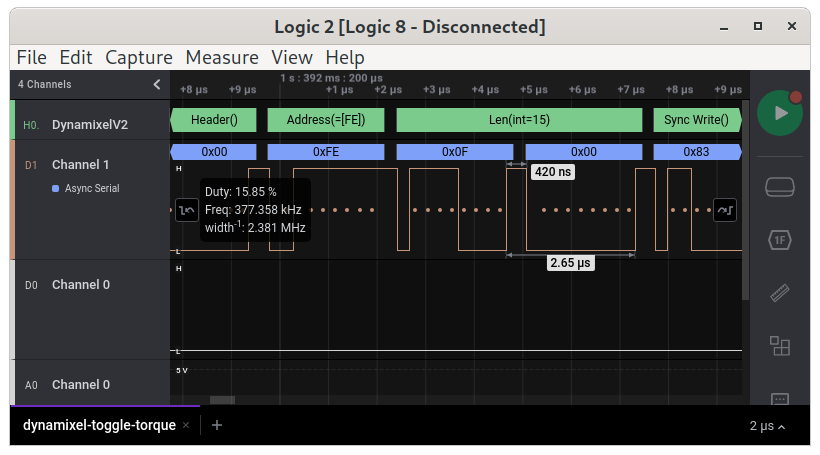
Decoded Dynamixel protocol
I found Dynamixel protocol extension very useful and given there was no extension for F.Port yet, I decided to write my own. It was not hard to write. Saleae has extensive documentation about extensions. Extensions are publicly hosted on GitHub so there are plenty of examples to learn from. Extension code needs to be written in Python. Here is an example of my extension in action:
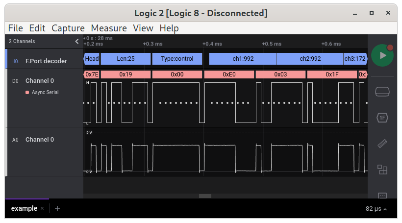
F.Port decoded channels
As you can see extensions can operate not only on bytes. For example, blue channel boxes ("ch1", "ch2", "ch3") span bits they represent. This aids a lot for debugging and understanding data. Here is an example of decoded "flags" bits:
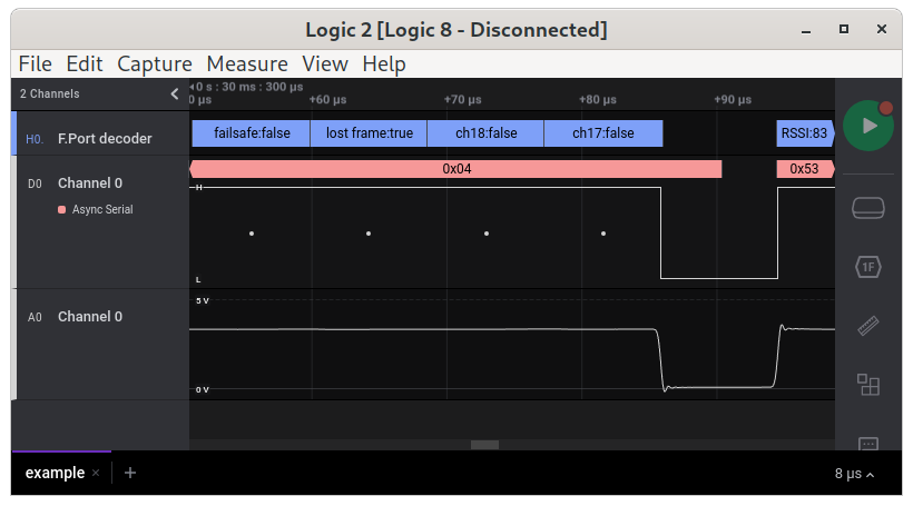
F.Port decoded flags
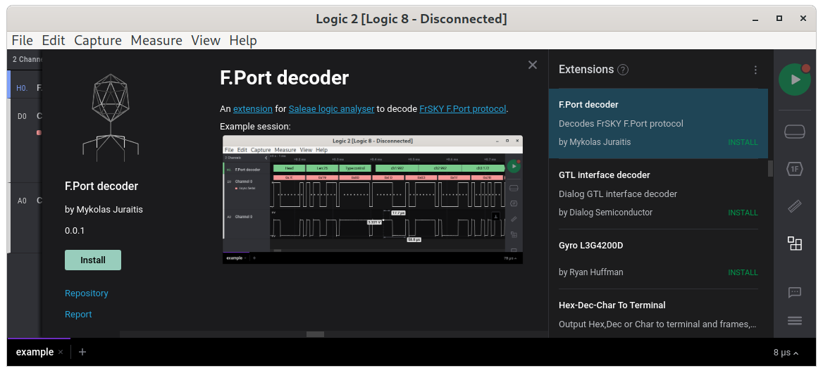
My "F.Port decoder" extension is already included in official extensions, so you can install it as any other with a single click:
F.Port decoder extension
I hope it will be useful for someone and I am looking forward to create more.